A few words about thermal bridges
Thermal bridges are parts of the building casing where the uniform thermal resistance is significantly reduced by:
Places where thermal bridges occur are exposed to significant reduction of the surface temperature of partitions, which may lead to surface condensation of water vapour and higher energy consumption needed to heat the room In a situation when the temperature of the cold surface drops below the dew point temperature, surface condensation of water vapour occurs, which may favour the development of an unfavourable microclimate in the room.

Thermotec reinforcement connectors
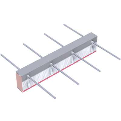
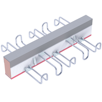
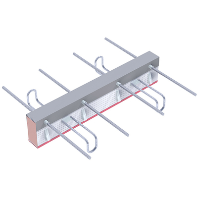
Thermotec reinforcement connectors are a universal and simple solution ensuring a secure connection of the balcony slab with the building structure. By replacing the full reinforced concrete cross-section with the connector consisting of insulation made of resole foam and elements of stainless steel, which is characterized by a much lower thermal conductivity than ordinary steel, the heat flux at the connection of the balcony slab with the ceiling is minimized.
Thermal resistance calculations
The calculation of parameters of energy losses through thermal bridges is carried out in accordance with PN-EN ISO 10211:2008, taking into account their linear and point heat transfer coefficients.
These coefficients are characterized by a significant variability of values depending on the design of the partition, the length of the connection, as well as the window and door openings and their insulation parameters. According to PN-EN ISO 10211:2008, the basis for determining the heat transfer coefficient can be the equivalent lambda coefficient, the values of which are presented on the following pages. The equivalent lambda coefficient allows to express the value of the thermal conductivity coefficient for an element consisting of different materials and can be used as a surrogate thermal conductivity coefficient in the three dimensional calculation of thermal bridges. The thermal resistance should be calculated in accordance with EN ISO 6946 and EN ISO 10211 and the guidance in EAD 050001-00-0301. The equivalent thermal resistance of the connector should be determined using numerical methods and detailed 3D models.
Fire resistance of buildings
The basic document defining fire safety requirements for residential ceilings is the ordinance which specifies general fire safety requirements for buildings.
Pursuant to paragraph 209 of the Ordinance, residential buildings belong to the ZL IV risk category for people and, depending on the height group, they can be assigned to the appropriate fire resistance class:
The fire resistance classes of the building are assigned the fire resistance class of building elements, which, in accordance with paragraph 216 of the ordinance, in the case of ceilings and walls, together with the resistance of the elements of the spandrel, corresponds to:
Buildings classified as other categories of risk to people should be considered in accordance with Chapter VI of the ordinance, but requirements for fire resistance of building elements do not exceed the A class. Requirements for the fire resistance class do not apply to buildings:
Fire resistance of Thermotec connectors
Based on the tests carried out at the Fire Research Laboratory of the Building Research Institute (Laboratorium Badań Ogniowych Instytutu Techniki Budowlanej), Thermotec reinforcement connectors with thermal insulation are available in variants with different fire resistance:
| Connector type |
Protection method |
Fire resistance class of the balcony slab |
| A, A1 | Two protection plates - bottom and top of the connector |
REI 240 |
| One protection plate on top of the connector |
REI 60 | |
| B | Two protection plates - bottom and top of the connector | REI 120 |
| One protection plate on top of the connector | REI 30 | |
| C | Two protection plates - bottom and top of the connector | REI 120 |
| One protection plate on top of the connector | REI 30 | |
| D | Two protection plates - bottom and top of the connector | REI 120 |
| One protection plate on top of the connector | REI 30 | |
| E, E1 | Two protection plates - bottom and top of the connector | REI 120 |
| One protection plate on top of the connector | REI 60 | |
| F | Two protection plates - bottom and top of the connector | REI 120 |
| One protection plate on top of the connector | REI 60 |
Confirmed quality
Thermotec balcony connectors have the National Technical Assessment issued by the Building Research Institute (Instytut Techniki Budowlanej - ITB). Their quality is confirmed by the Declaration of Performance and the Certificate of Factory Production Control issued by the Building Research Institute (ITB) in Warsaw.
Concrete and covering requirements
The minimum concrete class required for connectors for strength reasons is C20/25. Independently, however, requirements included in Annex F of PN-EN 206-1 specifying the minimum class of concrete depending on the class of the environment should be taken into account.
Serviceability limit state requirements
Elements connected to the structure with Thermotec connectors should meet the requirements of Chapter 7 of PN-EN 1992-1-1:2004. The deflection of the element caused by a quasi-constant combination of loads should not exceed 1/250 of the element span. Recommended maximum overhangs of cantilever plates are presented on 4 page in catalog "Balcony connectors-Thermotec".
The deformation of the balcony connector can be determined in a simplified way using the expression:
u=(M*L)/k
where:
M – the resulting bending moment from a quasi-constant combination,
L – the cantilevered overhang,
k – the cantilevered rotational stiffness specified in tables concerning the load capacity of connectors.
The exact determination of the deformation of the balcony and the required assembly lift should be determined on the basis of calculations madeby the finite element method.
Computational assumptions
When calculating by the finite element method, the following support conditions should be considered:
It is recommended to perform calculations using the finite element method, taking into account the actual support conditions for the balcony and the ceiling slab to which it is connected. “Manual” calculations can only be used for simple cantilever geometry and continuous support.
Expansion joints
Distances between the expansion joints should not exceed the values specified in the figure below.

Construction of Thermotec connectors

1. Insulation
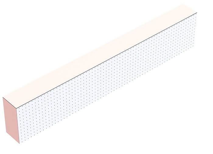
Thermotec connectors are a synthesis of the best solutions of modern construction. Insulation properties of Thermotec® depend on the core of our product, i.e. a rigid resole foam in a double-sided micro-perforated cladding containing aluminium. The main advantage of the resole foam used in Thermotec® is the thermal conductivity coefficient λ = 0.020 W/m·K, thanks to which we can achieve a significant reduction of the insulation thickness.
The other advantages include:

2. Fireproof part
The fire protection of our product is made of the highest qualitycalcium silicate boards. During tests at the Building Research Institute (ITB), A Thermotec® A connectors obtained the REI 240 fire resistance class!
Other advantages of fire rated boards include:

3. Construction part


Thanks to the use of the Extrea Tec system in Thermotec®, it was possible to obtain its advantages, which include:
Scheme of retrofitting and determination of the load capacity of slabs using hangers transferring shear forces
The scheme for determining the load capacity and retrofitting the hangers transferring shear forces to the load capacity of the systems of more hangers, the control circuits of which overlap, and plates with a higher degree of reinforcement than the minimum one, should be checked in accordance with the provisions of PN-EN 1992-1-1 and the following assumptions, that: the steel load capacity of a single hanger does not exceed 41.3 kN.


dm – the mean static useful height of the slab, where dm= (dx+dy)/2,
u – he critical perimeter at 1.5d – determined as shown in Figure 1,
fck – characteristic compressive strength of concrete,
β – the factor that takes into account the non-axial symmetric distribution of shear forces, for the plate edge β=1,4.


